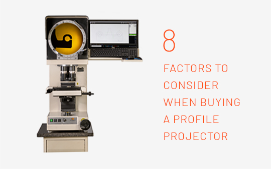
Selecting The Right Profile Projector
Part Weight
The first thing to consider when selecting a profile projector is the part weight, which decides whether the Profile Projector would have a glass or a metal workstage and correspondingly whether the light path will be vertical or horizontal. For example, for a glass work stage, the light path is vertical (vertical profile projector), on the other hand on a metal work stage, the light path is horizontal (horizontal profile projector). Below is a table that lists the most suitable profile projector type depending on the weight of the part to be measured.
| Part weight range | 1gm<x<15Kgs | 15Kgs<x<25Kgs | 25Kgs<x<150 Kgs |
| Profile Projector Type | Vertical Benchtop | Vertical Floor Standing | Horizontal |
Part Size
The second thing to consider is the part size, which decides the work stage measuring distance and the screen size of the profile projector. Parts on a profile projector are measured by marking a reference point and then moving the work stage along the shadow (on the screen) and thus the dependence. Below is a reference table that lists the part sizes and the required screen size. As you will see, the screen size has two tables, one for the complete part to be visible on the screen and the other for a portion of the part to be visible at any given instance. The calculations are done considering the standard 10X magnification lens
| Part Size (mm) | Work Stage Measuring Distance -Standard (mm) | Screen Size mm (10X Mag)Complete part visible | Screen Size mm (10X Mag) Portion of the part visible |
| 1<x<25 | 50 x 50 | 300 | 300 |
| 25<x<35 | 50 x 50 | 400 | 300 |
| 35<x<45 | 50 x 50 | 600 | 300 |
| 45<x<60 | 100 x 100 | 600 | 300 |
| 60<x<80 | 100 x 100 | 800 | 400 |
| 75<x<95 | 100 x 100 | NA | 600 |
| 95<x<145 | 150 x 150 | NA | 600 |
| 145<x<195 | 200 x 200 | NA | 800 |
Feature Size
Since the profile projector will be used for measuring different features on the parts, you need to know the required lens magnification which is dependent on its minimum attainable resolution.
| Lens Magnification | Minimum Attainable Resolution (microns) |
| 5x | 50 |
| 10x | 30 |
| 20x | 20 |
| 50x | 8 |
| 100x | 0.2 |
Application
Depending on the end-use of the profile projector, one may or may not need additional overlays, DROs, or Metrology Software. Below is a table that lists the end-use and the corresponding items required for the same.
| Purpose | Add-ons required |
| Part Comparisons | No DROs/Software |
| Measuring Positions and Distances | Basic DRO |
| Measuring Circles and Angles in addition to distances | Geometrical DRO and Rotary Encoders |
| For Obtaining Measurement Reports and Part Drawings for the measured circles, angles, and distances | Metrology Software and Rotary Encoders |
Operator Skill Level
Measurements using a profile projector require the operator to visually identify and select an edge to provide input to the DRO or metrology software. The operator skill level here is important not only for precise measurements but also for the time it takes for performing the measurement steps. If a well-skilled operator cannot be made available, it is best to use an additional opto-edge sensor that will automatically detect edges to perform measurements.
Erect and Un-reversed Profile Image
A regular profile projector is so designed to project an inverted and reversed shadow on the screen. For symmetrical parts, this design works perfectly well. However, if you need to have a fully corrected system, so that you see an erect and un-reversed profile image on the screen, you need to specifically mention the requirement to the manufacturer, who will then include ‘corrected optics’ for the same.
Surface Features Inspection and Measurement
The standard profile projector uses a bottom light to create a shadow of the part on the screen, however, if you need to view and measure features on the surface you need to mention that requirement to the manufacturer, who will then provide a top light illumination.
Deep Cavity Inspection and Measurement
Normally the top illumination on the part is done through top ring lights, which are good for surface illumination but do not illuminate the deep cavities present on the surface as the light rays fall obliquely and do not reach the cavities. To resolve the issue, a co-axial lens and illumination are used, which allow for lighting and viewing of deep cavities.

