Optical Comparators Metrology
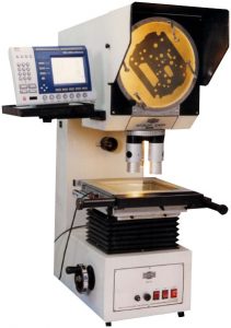
An Optical Comparator projects the magnified image of the object onto a glass screen transforming the visual impression into a physical reality in terms of dimensions and geometric forms which can then be compared to physical masters, graduate rulers to find the tolerances of the manufactured object. Moreover, light reflection, using either normal or oblique illumination enables observation of surface characteristics.
The primary objective of an optical comparator is to produce an undistorted and magnified shadow of the object on a screen. A high-intensity light system is followed by a collimating lens which refracts the light into a beam with equal intensity parallel rays. The resulting light falls on the object to be measured and further onto a projection lens system that magnifies and transmits the object contour onto a viewing screen.
The optical path in an optical comparator can either be vertical or horizontal. The former is best suited for light to medium weight parts, while the latter works best for horizontal parts.
Optical Comparators are equipped with cross roller guide-based work stages that have controlled transverse motions by means of a micrometer screw, rotary handwheel, or stepper motors. The X-Y motion of the stage moves the part and its shadow on the screen so that the user keeping an eye on the shadow edges moves the part and the travel distance is recorded and displayed on a DRO or Metrology Software.
Following are some of the important Applications of Optical Comparators in Metrology:
- Measurement of several linear and angular dimensions in a single set-up, thus assuring the proper interrelation between the consecutively inspected dimensions.
- Inspection of the part in accordance with the principles of true position tolerancing by using a layout chart on the screen with tolerance zones.
- Multiple dimensions on large parts can be inspected by observing consecutively the adjoining sections of the object.
- Geometric interrelations such as parallelism, squareness, coaxiality can be reliably inspected by establishing the starting stage of the measuring process an appropriate datum e.g. the axis of the part’s image.
- All major dimensions of external screw threads, such as diameters, flank angle, lead, root and crest form etc. can be inspected.
- The proper location and connections of element , leads and terminals of modern printed circuits can be inspected at high magnification.
- Functionally meaningful mating conditions, such as the location of the contact areas on the flanges, can be measured.
- Optically inaccessible areas of a part can be inspected by creating and then measuring a replica that provides faithful duplication of the surface contour with excellent detail definition.
- Clearances in assemblies which are accessible to optical viewing can be inspected by applying a force consecutively or in opposite directions.
Given the numerous application of Optical Comparators in industrial metrology, these systems form an irreplaceable part of the quality control lab of a manufacturing unit.
Benefits of using Optical Comparators
- Optical Comparators are non-contact measuring equipment where no physical contact with the object to be measured is required, eliminating the errors caused by distortion that result when physical pressure is applied to the object.
- Optical comparators are wear free measuring systems that do not require regular check-up to rule out wear and tear of the equipment.
- Optical comparators enable quick and precise comparison of the projected image with the basic design form thereby saving time.
- Several dimensions and form characteristics of a specimen can be observed, compared and evaluated in a single setting making the measurements less tiresome.
- Analysis by a group of people is possible on optical comparators as the projected image can be simultaneously observed.
- Automated measurement routines can be created on a CNC optical comparator that can then be compared with the standard CAD data.
- Optical comparator can inspect Surface Characteristics by using surface illumination.


