Video Measurement Systems
Introduction to Video Measuring Systems
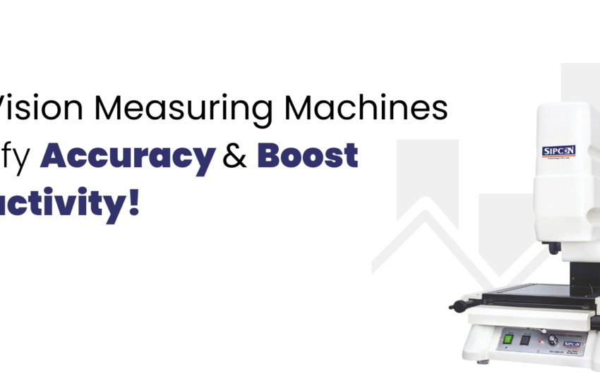
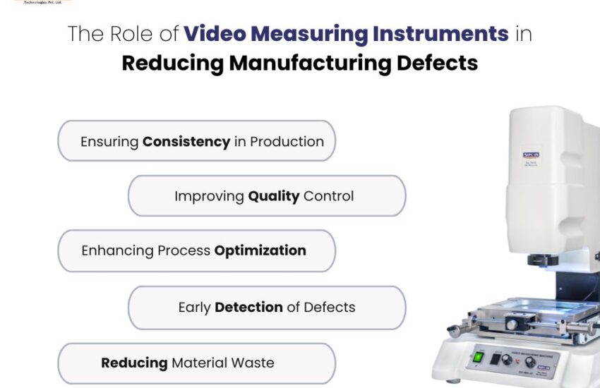
Video Measurement Systems also known as Vision Measuring Systems are used for quick and accurate 3d measurements of small parts mostly in the quality control process of a manufacturing plant.
History of Video Measuring Systems
Video Measurement Systems have been around for more than 40 years, with the earlier versions being an adaptation of the profile projector. However, the first proper video measurement system developed in 1977 by View Engineering of USA, was an automated measurement system complete with motorised XYZ stages, video monitor and a metrology software. Over the years, the system kept on evolving on different lines and in 1986, Optical Gaging Products (USA) introduced the first video measurement system to incorporate a graphics workstation along with laser and touch probe sensors. The 1990s saw the introduction of colour camera, zoom lens, faster processors, improved metrology software with ability to import CAD files and provided measurement results for statistical process control.
Basics of Video Measurement Systems
Video Measurement Systems, also sometimes known as optical co-ordinate measuring machines, are specially designed for precision dimensional measurements of small parts. The measurements are purposely done offline to minimize environmental variables.
The system enables 3Dimensional measurements of small parts by using a video camera and lens system to optically magnify the part image and then identifying the edges using a metrology software so as to measure dimensions with the help of glass scales and encoders.
Principle of Video Measurement Systems
Video Measuring Systems don’t directly measure the parts but instead measure the images of the part. This necessitates a precise reproduction of the part to an image using state-of-art optics and lighting.
Also, these systems use motion for measurements i.e the part is placed on a stage which can move iy in X-Y directions and the displacement is measured using glass scales and encoders. An ideal system would have the best straightness of travel, optimal stage speed and best-in-class positional resolution to provide accurate measurements. For z-axis measurements, a motorised zoom lens sends focused images on different planes to the metrology software which then calculates the height/depth of the feature in the part.
Making the above possible is a stable and damped mechanical structure, usually made of granite and steel, on which optical and mechanical parts are integrated. This ensures that no part of the video measuring system moves independently of the other because if it does it will greatly affect the measurements.
A Video Measurement System can be manual or CNC to suit specific applications. For example if large number of dimensions need to be measured then a CNC system is best suited. In a CNC version, the XY stage movement is motorised and the Z axis has a motorised zoom lens. All measurement steps are fed into the metrology software which makes a program of the routine and can then automatically perform measurements.
Moreover, a Video Measuring System can be integrated with a touch probe and a laser system for specific applications. For complex 3D measurements, a touch probe can reach out to hidden features that cannot be accessed by illumination. Similarly for applications where more accuracy is required in depth measurements, the laser is the best option.
Types of Video Measurement Systems
Video Measurement Systems are primarily of two types: Manual and Automatic
Manual : In manual systems, the part is moved on a manually operated workstage. The Z-axis zoom lens can however be motorised. The metrology software automatically detects edges and guides the user to move the stage accordingly.
Automatic : In automatic versions, the part is moved on motorised CNC stages and the Z-axis zoom lens is motorised. A user can create measurement routine, which can be saved and then repeated. This not only speeds up the measurement process but also ensures that the measurements are performed in the same way for every part, thereby eliminating operator to operator measurement errors.
Accuracy of Video Measurement Systems
The degree of conformity of a measured or calculated value to its actual or specified value. Accuracy, is the single most important parameter that defines the value of a video measurement system. According to the dimensional and geometrical product specifications and verification standard ISO 10360-2, the accuracy specifications are expressed in the following form.
Ex = [k + (multiplier * L) / 1000] μm
Where:
E= the maximum permissible error, in microns, under the given conditions
X= 1, 2, or 3 refers to single-, two-, or three-axis accuracy, respectively
k= systemic or inherent machine error that is not length-dependent
multiplier = a constant that defines the travel-dependent error
L= the length of travel over which the accuracy specification is desired, in millimeters
μm= microns, the accuracy unit of measurement
Calibration of Video Measurement Systems
Repeated use and external factors can make a video measuring system go out of calibration after some time. Therefore it is advisable to get the system re-calibrated every year by an experienced professional. A typical calibration procedure involves the check of the following:
- Table flatness with respect to the optical axis
- Focus squareness with respect to the optical axis.
- Par-centrality of zoom lens
- Accuracy of Edge Detection
- Stage Squareness of the X/Y axis
- Linear calibration of the of the X/Y axis and the Z-axis
Error Types in Video Measurement Systems
Errors can creep in from multiple sources in a Video Measurement System. Given the high accuracy and repeatability required of these systems it is important to understand the sources of these errors so that corrective actions can be taken to eliminate them.
- Optical Distortion: It’s a lens error, in which the captured image is distorted due to imperfections of the lens.
- Video/Image Errors: These are caused by imperfections in the chip geometry and spatial variations on the detector surface of the CCD/CMOS image sensors of the digital camera. Cameras with good Signal to Noise ratio, pixel symmetry and thermal stability will give minimum errors.
- Calibration Errors: The system is incorrectly calibrated by the technician.
- Quantization Errors: The glass scale and the encoders do not give the correct position of the scale. It requires calibration of the measurement system by a technician.
- Straightness Errors: The workstage X-Y movements are non-linear, a movement in X-direction also causes a movement in Y-direction.
- Pitch Error: Workstage moves in an arc instead of a straight line.
- Orthogonality Error: Two or more of three axis of the system are not at 90 degrees to each other.
- Part Thermal Stress Errors: Parts on which measurements are to be done should be thermally soaked in the controlled environment of the measurement lab for about 24 hours before measurements are carried out.
- Errors due to External Environment: Variations in temperature, pressure and humidity can cause deformation of the body of the video measurement system if high thermal coefficient materials of construction are used.
Metrology Software Features for Video Measurement Systems
A typical video measurement system software needs to have the following essential features that will make sure that the measurements are accurate. These features are as follows:
- Image Enhancement : The software should have excellent filtering and calibration tools. While tools for filtering are used to sharpen edges, remove noise or extract frequency information, the calibration tools removes non-linear and perspective errors caused by lens distortion and camera placement.
- Image Inspection: The color or pattern matching tools make use of changes in intensity to check the presence of part or feature.
- Features Location: Edge detection, grey scale, pattern-shape-color matching are some of the tools used to locate features in an image. Locating features is essential for aligning objects or determining exact object placement.
- Feature measurements: Edge detection and geometric function tools are used for measuring distances, diameters, angles etc.


